
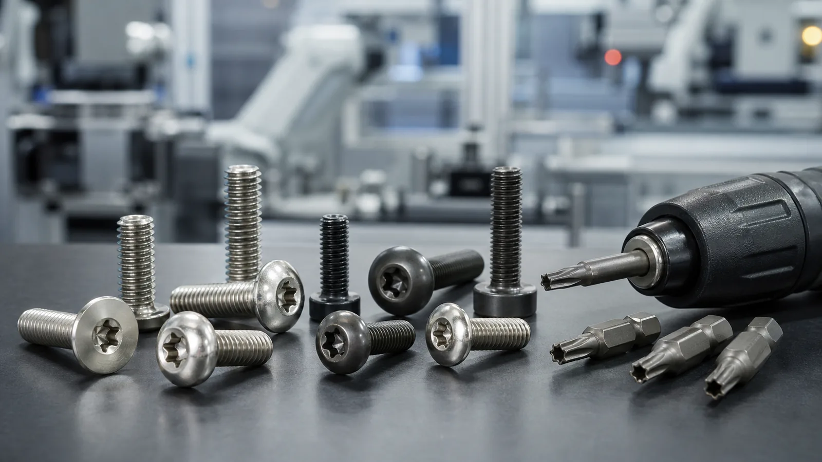
A Torx screw can improve tool engagement, yet the drive shape alone will not stabilize an assembly line. Recess quality, driver alignment, bit wear, head geometry, material, finish, and torque control still decide whether every screw seats cleanly. Problems often begin when a buyer specifies only “Torx” and leaves the drive size, standard, inspection method, and joint requirements undefined.
This guide separates the common trade name from the generic hexalobular feature and shows how engineers should specify six-lobe drive screws for manual, automated, and serviceable assemblies.
Torx and hexalobular are related but not identical terms
Torx is a well-known trade name for a six-lobe drive system. In engineering drawings, hexalobular internal drive is the generic description commonly associated with the geometry. ISO 10664 specifies the shape, basic dimensions, and gauging method for the internal driving feature. The ISO page also states that this drive-feature document is intended to support inspection, not to serve as a complete screw manufacturing standard.
That distinction prevents a frequent purchasing error. A recess standard does not define the screw’s head style, thread, material, mechanical properties, finish, or overall tolerances. A complete specification may reference a product standard for the screw and a drive-feature requirement where needed. Trademarked variants and security versions should be identified accurately because similar-looking drivers are not always interchangeable.
Why six-lobe drives are considered for production assembly
The rounded lobes provide a positive drive interface with less tendency for the bit to ride out than a conventional cross recess when the bit is correct and aligned. The geometry can transmit installation torque through multiple contact regions, which is useful in compact heads. It also reduces the operator’s need to apply the large axial force often associated with keeping a cross driver engaged.
These advantages are conditional. A shallow, poorly filled, off-center, or coated recess can negate them. Angular misalignment can concentrate load at only part of the profile. An undersized, rounded, or incorrectly identified bit can damage the lobes. In automatic assembly, feeder orientation and bit-to-recess location still need a controlled approach sequence.
- Select the drive size from the governing screw design and required torque, not from visual similarity.
- Control bit runout, axial alignment, approach speed, and replacement intervals.
- Evaluate recess fill, depth, concentricity, burrs, coating, and contamination during approval.
- Record the torque-angle or torque-time signature when the line needs traceable seating control.
Match the drive to head geometry and clamp demand
A six-lobe recess can fit button, pan, countersunk, cylindrical, flange, and other heads, but each head offers a different depth and material volume around the recess. A small countersunk head may have little room between the lobes and the conical bearing surface. A low button head trades projection for recess depth. A taller cap head provides more drive engagement but may violate the product envelope.
Start with required clamp load and the screw’s mechanical capacity. Then check whether the chosen head and drive can transmit installation torque with a practical margin. If field technicians must remove the screw after corrosion, paint, threadlocking adhesive, or thermal cycling, removal torque deserves its own test. A drive that works for initial factory seating may be inadequate for later service.

Torx versus hex socket in real equipment
Both internal hex and six-lobe drives can provide compact, positive engagement. Hex sockets are widely available, familiar to service teams, and supported by broad standard product ranges. Six-lobe drives may offer better contact behavior in some head envelopes and can help reduce recess damage under controlled tooling. The better choice depends on supply continuity, existing tool families, assembly access, torque, contamination, and service expectations.
Tool standardization often matters more than a theoretical drive advantage. Adding one uncommon bit size to an otherwise standardized product can create line-change errors and field-service frustration. Conversely, assigning a distinct drive family to a controlled station can reduce the chance that an operator installs the wrong fastener. Treat tooling as part of the bill of process, not an afterthought to the bill of materials.
Design an assembly process around engagement
The driver must reach full, repeatable engagement before significant torque is applied. In a recessed pocket, verify that the bit holder clears adjacent walls. On a flexible part, support the joint so axial driver force does not deflect the assembly. For an automatic spindle, define the search or seating motion, maximum engagement force, speed transitions, torque strategy, and fault limits.
High speed is not always faster in practice. Excessive approach or rundown speed can increase misalignment, cross-threading, heat, and overshoot. The appropriate settings depend on thread type, material, coating, joint stiffness, and driver control. Establish them with production-representative trials and retain samples from the dimensional and friction limits of the approved fastener range.
Recess manufacturing and inspection deserve drawing space
The recess is usually formed during heading, so punch condition, material flow, lubrication, head volume, and tool alignment influence the result. Small screws and shallow heads provide less process margin. Rounded lobes, incomplete fill, cracks, double hits, eccentric recesses, and excess coating can cause poor bit engagement even when an informal top-view measurement looks acceptable.
Functional gauging is preferable to inventing a few incomplete dimensions around a complex profile. ISO 10664 includes a gauging method for the internal feature, while the full part still needs the checks required by its product drawing. Inspection may include head dimensions, recess gauge acceptance, depth, wobble or concentricity criteria, thread gauges, length, material, mechanical tests, finish thickness, and visual workmanship.
Account for material, finish, and friction
Drive performance cannot be separated from material and finish. A harder fastener may resist local deformation, but the required property class and heat treatment must suit the complete product specification. Stainless steel supports corrosion resistance but brings different friction and galling considerations. Coatings can alter friction, fill a small recess, or change bit fit when their thickness is not controlled.
Do not publish one generic torque for every Torx screw of a nominal size. Torque-to-preload behavior varies with material, underhead bearing, thread finish, lubrication, mating thread, and reuse. When clamp load matters, obtain data for the actual fastener system or validate with a test method defined by the joint engineer. Tool torque should be adjusted only with evidence from the intended process.
Security pin versions require a separate decision
A center-pin security recess can discourage casual removal, but it does not make an assembly universally tamper-proof. The pin reduces available tool geometry and requires dedicated bits. Debris, coating, and shallow engagement may become more critical in small sizes. Define whether the purpose is access control, vandal resistance, warranty indication, or simple tool differentiation, then test both installation and authorized removal.
What to send in a Torx screw RFQ
- State whether the requirement is a licensed Torx system, a generic hexalobular internal drive, or a specific security variant.
- Provide the screw product standard or full drawing, including head, thread, length, point, tolerances, and drive size.
- Define material, mechanical properties, heat treatment, finish, corrosion requirement, friction condition, and restricted substances.
- Give target seating and removal conditions, driver type, bit access, speed, alignment, joint materials, and service cycles.
- Specify recess gauging, critical dimensions, visual criteria, traceability, sample approval, packaging, and annual quantity.
XiYu Precision can review a drawing for custom precision screws, including nonstandard heads and drive features. See the security screw capabilities, factory capabilities, and custom screw catalog before submitting an RFQ. For the generic internal feature, consult the current ISO 10664 record and the applicable full product standard.
Frequently asked questions
Is Torx the same as hexalobular?
Torx is a trade name associated with six-lobe drive systems, while hexalobular is the generic geometric description used in standards such as ISO 10664. A drawing should identify the exact required system and applicable product specification.
Do Torx screws eliminate cam-out?
They can reduce the tendency for the driver to ride out compared with some cross recesses, but they do not eliminate installation failures. Incorrect bits, shallow or defective recesses, misalignment, wear, contamination, and excessive torque can still damage the drive.
Can a Torx bit be used in any six-lobe recess?
Do not assume interchangeability from appearance. Confirm the drive family, variant, and size. Standard Torx, Torx Plus, external drives, and security pin versions can require different tools.
What should be inspected on a Torx screw?
Inspect the complete fastener plus the drive. Typical checks include functional recess gauging, recess depth and condition, head dimensions, thread gauges, length, material, mechanical properties, finish, and visual workmanship.
Specify the drive, tool, and joint as one system
Torx screws are useful when a compact drive and repeatable engagement support the assembly, but the name is not a complete specification. Identify the exact six-lobe system, select a head with enough drive capacity, control manufacturing and coating, and validate the real tool path. That approach improves production reliability without overstating what the recess geometry can do by itself.